Experiment No: 1 - Alcohol Detection and Engine Locking System Using Arduino Uno

Alcohol Detection and Engine Locking System Using Arduino Uno
Abstract
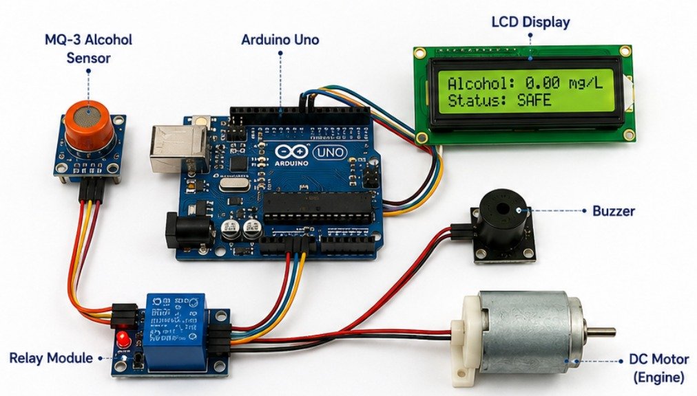
The Alcohol Detection and Engine Locking System is a smart vehicle safety project designed to reduce road accidents caused by drunk driving[cite: 1]. It uses an MQ-3 alcohol sensor to detect the presence of alcohol in the driver’s breath[cite: 1]. If the detected alcohol level exceeds a predefined limit, the Arduino Uno prevents the engine from starting by controlling a relay module[cite: 1]. At the same time, a buzzer and LED provide warning indications[cite: 1]. The system allows normal engine operation only when the alcohol level is within the safe limit[cite: 1].
Project Description
This project is developed to improve vehicle safety by automatically detecting alcohol consumption before the vehicle starts[cite: 1]. The Arduino Uno continuously monitors the output of the MQ-3 alcohol sensor and controls the engine through a relay module[cite: 1]. If alcohol is detected above the preset threshold, the relay disconnects the engine and activates both the buzzer and LED to alert the driver[cite: 1]. The project demonstrates the practical implementation of embedded systems in automotive safety and is suitable for educational institutions, research laboratories, and embedded system training[cite: 1].
Components Required
- Arduino Uno[cite: 1]
- MQ-3 Alcohol Sensor Module[cite: 1]
- 5V Relay Module[cite: 1]
- DC Motor (Engine Simulation)[cite: 1]
- Active Buzzer[cite: 1]
- LED[cite: 1]
- 220Ω Resistor[cite: 1]
- Breadboard[cite: 1]
- Jumper Wires[cite: 1]
- USB Cable / 5V Power Supply[cite: 1]
- LCD Display[cite: 1]
Working Principle
The MQ-3 alcohol sensor continuously senses the alcohol concentration in the driver’s breath and sends an analog signal to the Arduino Uno[cite: 1]. The Arduino compares the sensor value with a predefined threshold[cite: 1]. If the alcohol concentration is below the safe limit, the relay remains activated, allowing the DC motor (engine) to operate normally[cite: 1]. When the detected alcohol level exceeds the threshold, the Arduino immediately deactivates the relay, preventing the engine from starting[cite: 1]. Simultaneously, the buzzer sounds and the LED turns ON to alert the driver[cite: 1]. The system continuously monitors the sensor readings and restores normal operation once the alcohol level returns to a safe range[cite: 1].
Experiment No: 2 Driver Drowsiness Detection System Using ESP32-CAM
Driver Drowsiness Detection System Using ESP32-CAM
Abstract
The Driver Drowsiness Detection System is an intelligent vehicle safety project designed to detect signs of driver fatigue and prevent road accidents. The system uses an ESP32-CAM module to continuously monitor the driver’s face and eye movements. Image processing algorithms analyze whether the driver’s eyes remain closed for a specific duration. If drowsiness is detected, the system immediately activates a buzzer to alert the driver. This project demonstrates the application of computer vision and embedded systems in enhancing road safety.
Project Description
This project is developed to improve driver safety by monitoring the driver’s alertness in real time. The ESP32-CAM captures continuous images of the driver’s face and processes them to detect eye closure and fatigue. If the driver’s eyes remain closed beyond a predefined time, the system identifies it as drowsiness and triggers an alarm through a buzzer. The project is suitable for automobiles, research laboratories, and embedded vision applications, providing an effective solution for reducing accidents caused by driver fatigue.
Components Required
- ESP32-CAM Module
- FTDI Programmer (USB to Serial Converter)
- Active Buzzer
- LED
- Jumper Wires
- Breadboard
- USB Cable
- 5V Power Supply
Working Principle
The ESP32-CAM continuously captures images of the driver’s face and processes them using an eye detection algorithm. During normal driving, the system monitors eye movements without triggering any action. If the driver’s eyes remain closed for longer than the predefined threshold, the ESP32-CAM identifies the condition as drowsiness. It immediately activates the buzzer and LED to alert the driver and encourage them to regain attention. Once the driver’s eyes reopen and normal conditions are restored, the alarm automatically stops, and the system continues monitoring continuously.
Experiment No: 3 Smart Dustbin Using Arduino Uno
Smart Dustbin Using Arduino Uno
Abstract
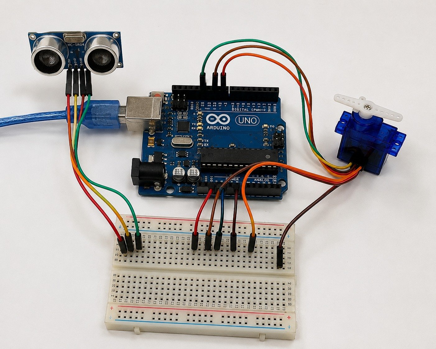
The Smart Dustbin Using Arduino Uno is an automated waste management system designed to improve hygiene by eliminating the need to touch the dustbin lid. The system uses an ultrasonic sensor to detect the presence of a person’s hand or any object near the dustbin. When an object is detected within the predefined distance, the Arduino Uno processes the sensor data and controls a servo motor to open the dustbin lid automatically. After a few seconds, the lid closes automatically. This project demonstrates the practical use of embedded systems, sensors, and automation in smart sanitation applications, making it suitable for homes, offices, hospitals, schools, and public places.
Project Description
The Smart Dustbin is an intelligent embedded system that promotes a clean and hygienic environment through touchless operation. The Arduino Uno acts as the main controller and continuously receives distance measurements from the ultrasonic sensor. When the sensor detects a hand or waste object near the dustbin, the Arduino sends a control signal to the servo motor, which rotates and opens the lid automatically. After a predefined delay, the servo returns to its original position, closing the lid without any manual intervention. This project reduces the spread of germs caused by touching the dustbin lid and provides a convenient waste disposal solution. It is widely used as an educational project to demonstrate sensor interfacing, servo motor control, and automation using embedded systems. The project can also be further enhanced by integrating IoT features, waste level monitoring, or automatic notification systems for smart city applications.
Components Required
- Arduino Uno
- Ultrasonic Sensor (HC-SR04)
- Servo Motor (SG90)
- Breadboard
- Jumper Wires
- USB Cable / 5V Power Supply
Working Principle
The ultrasonic sensor continuously measures the distance between the dustbin and nearby objects. When a hand or waste object is detected within the preset range, the Arduino Uno processes the sensor data and rotates the servo motor to open the dustbin lid. After a few seconds, the Arduino returns the servo to its original position, automatically closing the lid. The system continuously repeats this process whenever an object is detected, ensuring a clean and touchless waste disposal experience.
Experiment No: 4 Touchless Hand Sanitizer Dispenser Using Arduino Uno
Touchless Hand Sanitizer Dispenser Using Arduino Uno
Abstract
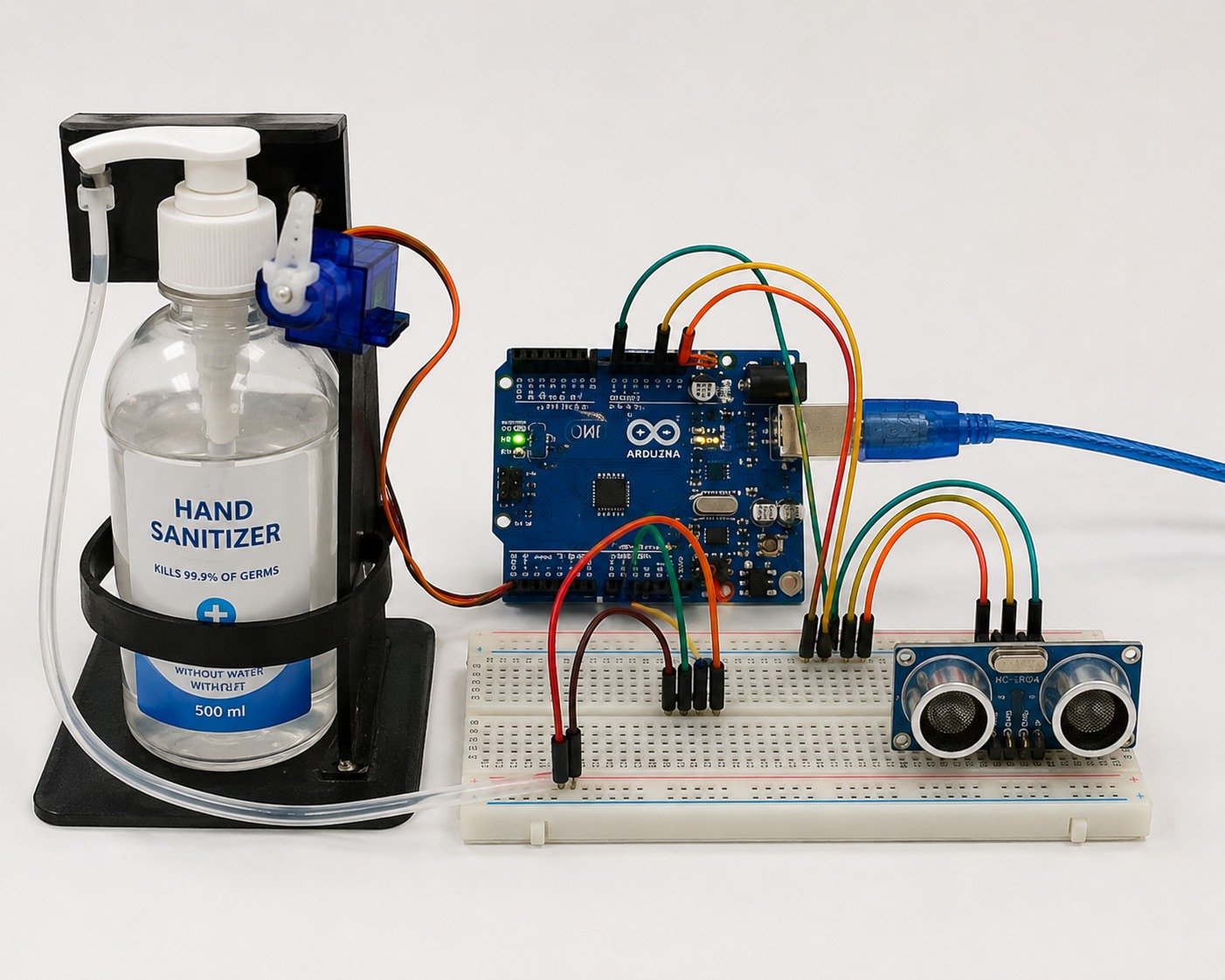
The Touchless Hand Sanitizer Dispenser Using Arduino Uno is an automatic hygiene system designed to provide a safe and contact-free method of dispensing hand sanitizer. The system uses an ultrasonic sensor to detect the presence of a user’s hand and automatically activates a servo motor to press the sanitizer pump. After dispensing the required amount of sanitizer, the servo motor returns to its original position. This project minimizes physical contact with the dispenser, helping to reduce the spread of germs and improve hygiene in public and private environments.
Project Description
The Touchless Hand Sanitizer Dispenser is an embedded automation project developed to promote better personal hygiene through contact-free operation. The Arduino Uno acts as the central controller and continuously monitors the ultrasonic sensor for the presence of a hand. When a hand is detected within the predefined distance, the Arduino activates the servo motor, which presses the sanitizer pump to dispense a fixed amount of liquid. After a short delay, the servo returns to its initial position, preparing the system for the next user. The project is easy to build, cost-effective, and suitable for use in hospitals, schools, offices, shopping malls, laboratories, and other public places where maintaining hygiene is essential.
Components Required
- Arduino Uno
- Ultrasonic Sensor (HC-SR04)
- Servo Motor (SG90)
- Hand Sanitizer Bottle
- Breadboard
- Jumper Wires
- USB Cable / 5V Power Supply
Working Principle
The system operates by continuously measuring the distance in front of the sanitizer dispenser using the ultrasonic sensor. When a user’s hand comes within the preset sensing range, the sensor sends the distance information to the Arduino Uno. The Arduino processes this input and generates a control signal to rotate the servo motor. The servo motor presses the sanitizer bottle pump, dispensing a fixed quantity of sanitizer onto the user’s hand. After dispensing, the servo motor automatically returns to its original position, and the system resumes monitoring for the next user. This touch-free operation ensures convenience, improves hygiene, and reduces the risk of cross-contamination.
Experiment No: 5 Smart Parking System Using Arduino Uno
Smart Parking System Using Arduino Uno
Abstract
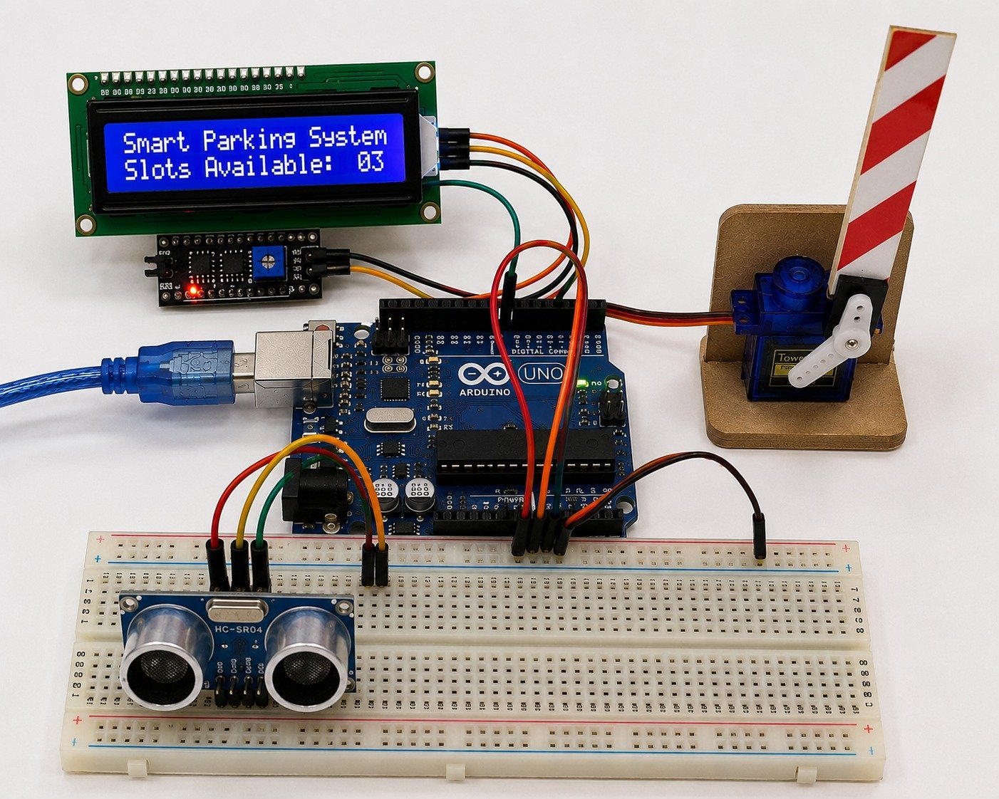
The Smart Parking System Using Arduino Uno is an intelligent parking management project designed to identify the availability of parking spaces and guide vehicles efficiently. The system uses ultrasonic sensors to detect the presence of vehicles in parking slots. Based on the sensor readings, the Arduino Uno updates the parking status and controls a servo motor to open or close the entrance gate. An LCD display shows the number of available parking spaces, helping drivers park their vehicles quickly and reducing traffic congestion.
Project Description
The Smart Parking System is an embedded automation project that simplifies vehicle parking by monitoring parking slot availability in real time. Ultrasonic sensors installed in each parking space continuously detect whether a slot is occupied or vacant. The Arduino Uno processes this information and displays the available parking spaces on an LCD screen. When parking spaces are available, the servo motor automatically opens the entrance gate to allow vehicle entry. If all parking slots are occupied, the gate remains closed and the display indicates that parking is full. This project is suitable for shopping malls, office buildings, hospitals, educational institutions, and residential parking areas.
Components Required
- Arduino Uno
- Ultrasonic Sensors (HC-SR04)
- Servo Motor (SG90)
- 16×2 LCD Display with I2C Module
- Breadboard
- Jumper Wires
- USB Cable / 5V Power Supply
Working Principle
The ultrasonic sensors continuously monitor the parking slots by measuring the distance to detect the presence of vehicles. The sensor data is sent to the Arduino Uno, which determines whether each parking space is occupied or vacant. The Arduino updates the available parking count on the LCD display in real time. When a vehicle approaches the entrance and parking space is available, the Arduino activates the servo motor to open the gate automatically. After the vehicle enters, the gate closes and the parking status is updated. If all parking spaces are occupied, the system keeps the gate closed and displays that no parking slots are available, ensuring efficient parking management.
Experiment No: 6 Reverse Car Parking Sensor Using Arduino Uno
Reverse Car Parking Sensor Using Arduino Uno
Abstract
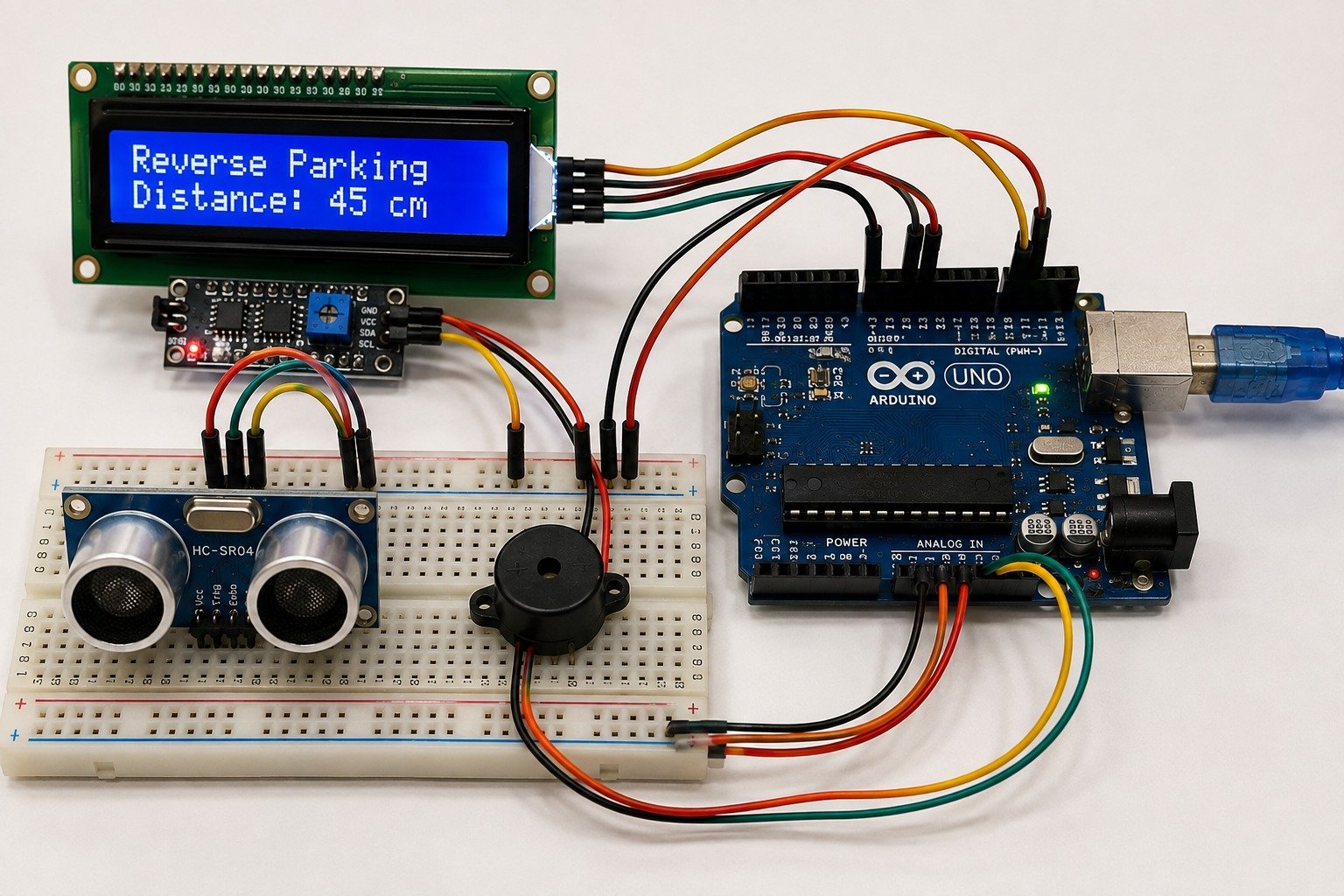
The Reverse Car Parking Sensor Using Arduino Uno is an intelligent vehicle safety system designed to assist drivers while reversing their vehicles. The system uses an ultrasonic sensor to detect obstacles behind the vehicle and accurately measure the distance between the vehicle and the object. The Arduino Uno processes the sensor data and provides audio warnings through a buzzer while displaying the measured distance on an LCD screen. As the vehicle moves closer to an obstacle, the warning sound becomes more frequent, helping the driver park safely and avoid collisions.
Project Description
The Reverse Car Parking Sensor is an embedded system developed to improve vehicle safety during reverse parking. The ultrasonic sensor continuously scans the area behind the vehicle and detects nearby obstacles such as walls, poles, or other vehicles. The Arduino Uno receives the sensor data, calculates the distance, and displays it on an LCD display for the driver’s reference. At the same time, the system generates audible alerts through a buzzer. The beep frequency increases as the distance decreases, providing a clear indication of how close the vehicle is to the obstacle. This project offers a simple, reliable, and cost-effective parking assistance solution and demonstrates the practical application of sensors and microcontrollers in automotive safety systems.
Components Required
- Arduino Uno
- Ultrasonic Sensor (HC-SR04)
- Active Buzzer
- 16×2 LCD Display with I2C Module
- Breadboard
- Jumper Wires
- USB Cable / 5V Power Supply
Working Principle
The ultrasonic sensor continuously transmits ultrasonic waves and receives the reflected echo from nearby obstacles. The Arduino Uno calculates the distance by measuring the time taken for the echo signal to return. The calculated distance is displayed on the LCD screen in real time. If the obstacle is at a safe distance, the buzzer remains OFF. As the vehicle approaches the obstacle, the Arduino activates the buzzer with increasing beep frequency to alert the driver. When the obstacle is extremely close, the buzzer produces a continuous sound, indicating that the driver should stop the vehicle immediately. The system continuously monitors the surroundings and updates the distance and warning signals, ensuring safe and accurate reverse parking.
Experiment No: 7 Home Security Alarm System Using Arduino Uno
Home Security Alarm System Using Arduino Uno
Abstract
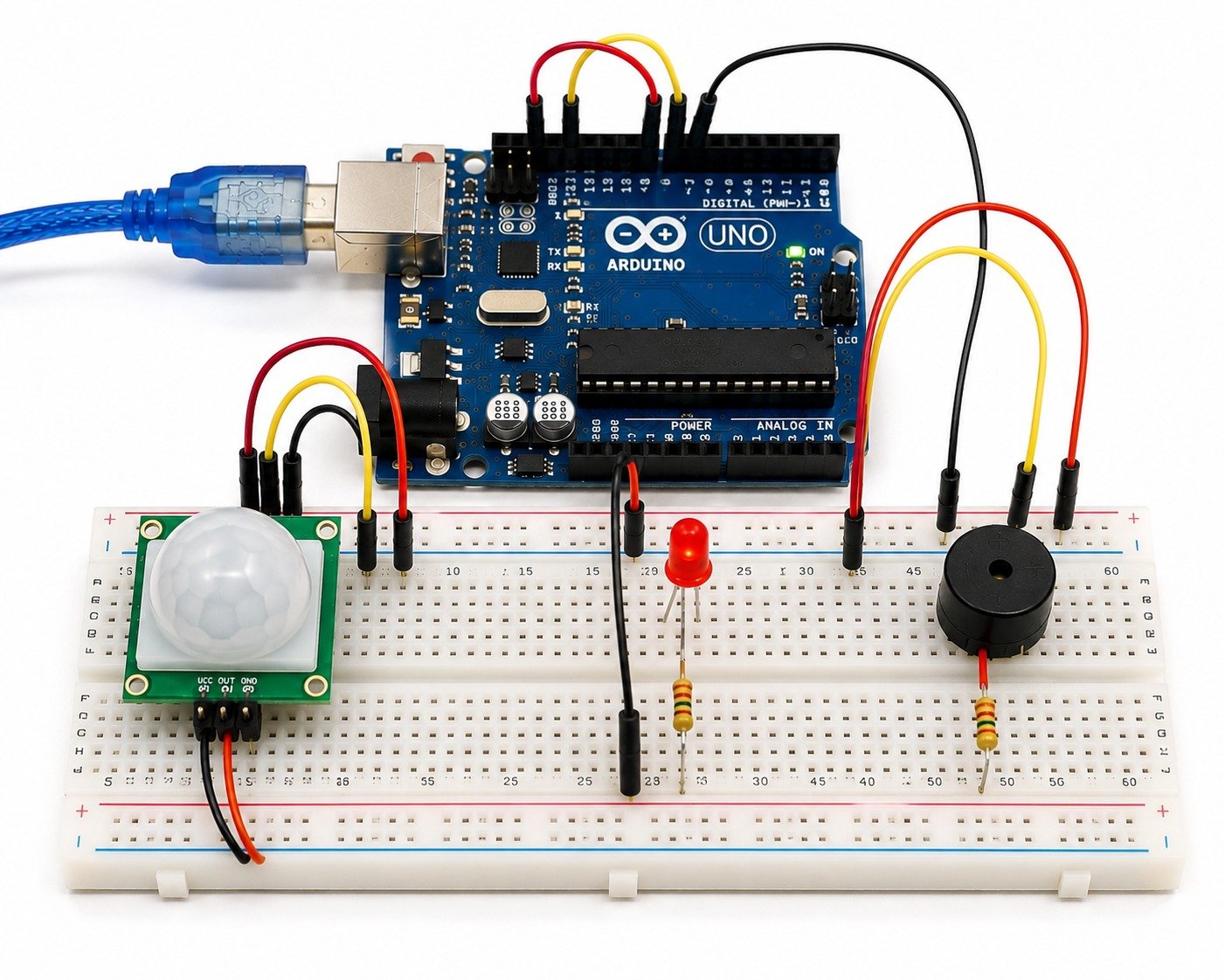
The Home Security Alarm System Using Arduino Uno is a smart security solution designed to protect homes and offices from unauthorized access. The system uses a PIR (Passive Infrared) motion sensor to detect human movement within a protected area. When motion is detected, the Arduino Uno immediately activates a buzzer and LED to alert the user. This project demonstrates the use of embedded systems in security applications and provides a simple, reliable, and cost-effective solution for intrusion detection.
Project Description
The Home Security Alarm System is an embedded security project that continuously monitors the surrounding area for human movement using a PIR motion sensor. The Arduino Uno acts as the main controller, processing the signals received from the sensor. When an unauthorized person enters the monitored area, the PIR sensor detects the motion and sends a signal to the Arduino. The Arduino then activates a buzzer and LED to provide both audible and visual alerts. The system can be installed at the entrance of homes, offices, laboratories, shops, and other restricted areas to improve security. This project is easy to implement, economical, and serves as an excellent demonstration of motion sensing and alarm automation.
Components Required
- Arduino Uno
- PIR Motion Sensor
- Active Buzzer
- LED
- 220Ω Resistor
- Breadboard
- Jumper Wires
- USB Cable / 5V Power Supply
Working Principle
The PIR motion sensor continuously monitors the surrounding area for infrared radiation emitted by human bodies. Under normal conditions, the Arduino Uno keeps the alarm system in monitoring mode. When a person enters the detection range, the PIR sensor detects the motion and sends a digital signal to the Arduino. The Arduino processes this signal and immediately activates the buzzer and LED, indicating the presence of an intruder. Once no motion is detected for a specified period, the alarm automatically turns OFF, and the system resumes monitoring for further movement. This continuous operation provides effective and reliable protection against unauthorized access.
Experiment No: 8 Automatic Street Light Control System Using Arduino Uno
Automatic Street Light Control System Using Arduino Uno
Abstract
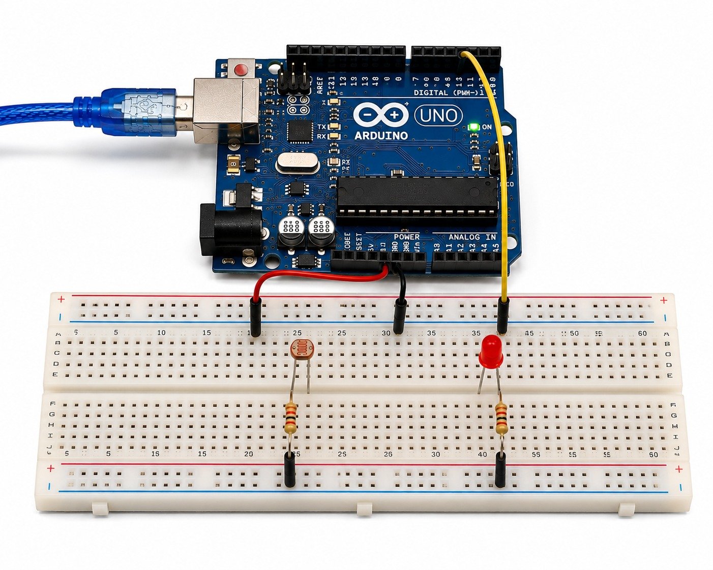
The Automatic Street Light Control System Using Arduino Uno is an energy-efficient lighting system designed to automatically control street lights based on the surrounding light intensity. The system uses an LDR (Light Dependent Resistor) sensor to detect day and night conditions. During the daytime, the street lights remain OFF to conserve energy, while at night, the Arduino Uno automatically switches the lights ON. This project demonstrates the practical application of embedded systems in smart city and energy management solutions.
Project Description
The Automatic Street Light Control System is a smart automation project that eliminates the need for manual operation of street lights. The LDR sensor continuously monitors the ambient light intensity and sends the corresponding signal to the Arduino Uno. Based on the sensor readings, the Arduino determines whether it is day or night and controls the street light accordingly. When the surrounding light intensity falls below the preset threshold, the street light turns ON automatically. As daylight increases, the Arduino switches the light OFF to reduce unnecessary power consumption. This project is suitable for streets, highways, parks, campuses, residential areas, and industrial premises, providing an efficient and cost-effective lighting solution.
Components Required
- Arduino Uno
- LDR (Light Dependent Resistor)
- LED (Street Light Simulation)
- 220Ω Resistor
- Breadboard
- Jumper Wires
- USB Cable / 5V Power Supply
Working Principle
The LDR continuously senses the intensity of the surrounding light and sends an analog signal to the Arduino Uno. The Arduino compares the received value with a predefined threshold. During daylight, when the light intensity is high, the Arduino keeps the LED turned OFF. As the surrounding light decreases during evening or night, the LDR resistance changes, causing the sensor value to drop below the threshold. The Arduino then switches the LED ON automatically, simulating a street light. The system continuously monitors the ambient light conditions and automatically controls the lighting, ensuring energy efficiency and reliable operation without human intervention.
Experiment No: 9 Smart Blind Stick Using Arduino Uno
Smart Blind Stick Using Arduino Uno
Abstract
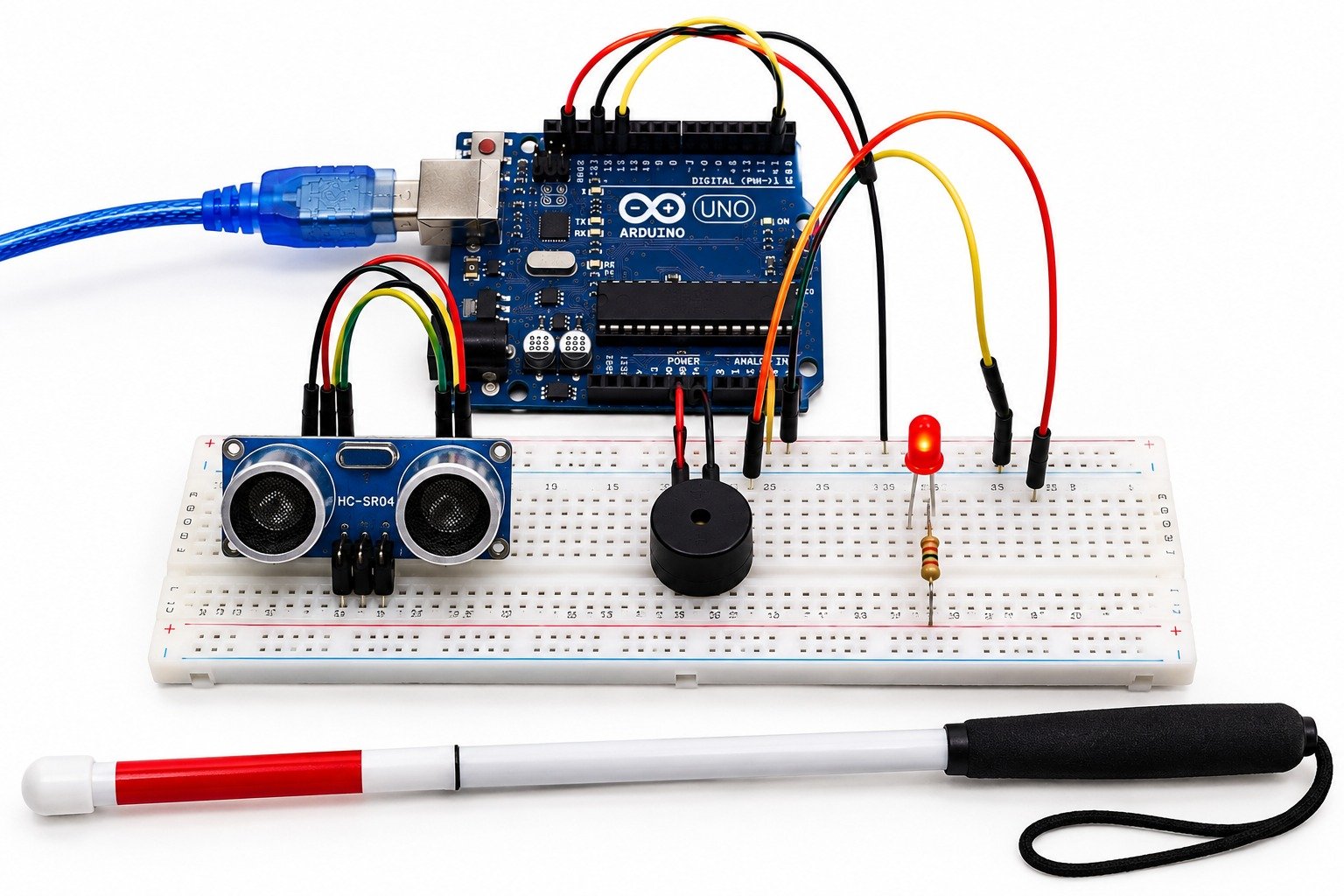
The Smart Blind Stick Using Arduino Uno is an assistive navigation system designed to help visually impaired people detect obstacles while walking. The system uses an ultrasonic sensor to identify objects in front of the user and alerts them through a buzzer. As the user approaches an obstacle, the warning sound becomes more frequent, enabling safe navigation and reducing the risk of accidents. This project demonstrates the use of embedded systems in developing affordable and reliable assistive technologies.
Project Description
The Smart Blind Stick is an intelligent mobility aid that enhances the safety and independence of visually impaired individuals. The Arduino Uno continuously receives distance measurements from the ultrasonic sensor mounted on the stick. When an obstacle is detected within the predefined range, the Arduino activates the buzzer to alert the user. The warning intensity increases as the distance between the user and the obstacle decreases, allowing the user to react in time and avoid collisions. The project is compact, easy to use, and suitable for educational demonstrations as well as real-world assistive applications.
Components Required
- Arduino Uno
- Ultrasonic Sensor (HC-SR04)
- Active Buzzer
- LED
- Breadboard
- Jumper Wires
- USB Cable / 5V Power Supply
Working Principle
The ultrasonic sensor continuously emits ultrasonic waves and measures the distance to nearby obstacles by receiving the reflected echo signal. The Arduino Uno processes the measured distance and determines whether an obstacle is within the preset range. If no obstacle is detected, the system remains idle. When an obstacle comes within the specified distance, the Arduino activates the buzzer to alert the user. As the obstacle gets closer, the buzzer beeps faster, providing a clear indication of the obstacle’s proximity. This continuous monitoring enables visually impaired users to detect obstacles in advance and navigate safely.
RFID-BasedExperiment No: 10 Smart Attendance System Using Arduino Uno
Experiment No: 10
RFID-Based Smart Attendance System Using Arduino Uno
Abstract
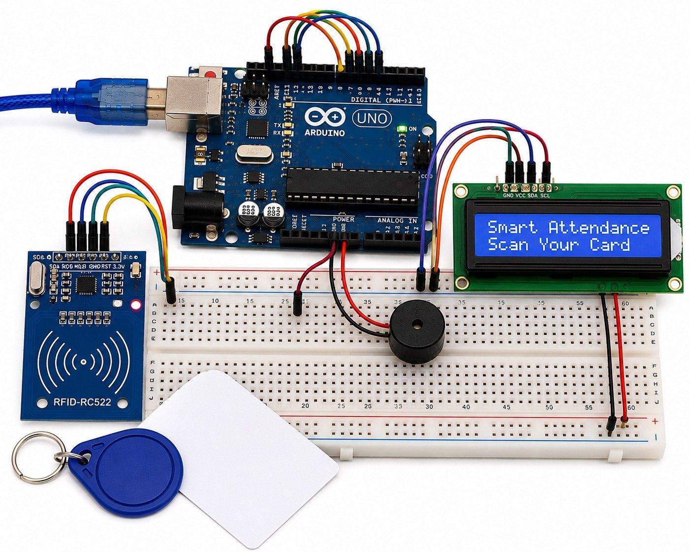
The RFID-Based Smart Attendance System Using Arduino Uno is an automated attendance management system designed to record attendance quickly and accurately. The system uses an RFID reader to identify authorized users through RFID cards or tags. When a valid card is scanned, the Arduino Uno verifies the card ID and records the attendance while displaying the user’s status on an LCD display. This project eliminates manual attendance marking, reduces errors, and provides a fast and secure attendance solution for educational institutions and organizations.
Project Description
The RFID-Based Smart Attendance System is an embedded application that simplifies the attendance process using Radio Frequency Identification (RFID) technology. Each user is assigned a unique RFID card containing an identification number. When the card is brought near the RFID reader, the reader sends the card information to the Arduino Uno for verification. If the card is authorized, the attendance is recorded, and a confirmation message is displayed on the LCD screen. A buzzer provides an audible indication of successful card detection. This project is suitable for schools, colleges, offices, libraries, and laboratories where accurate and efficient attendance management is required.
Components Required
- Arduino Uno
- RFID Reader Module (MFRC522)
- RFID Cards/Tags
- 16×2 LCD Display with I2C Module
- Active Buzzer
- Breadboard
- Jumper Wires
- USB Cable / 5V Power Supply
Working Principle
The RFID reader continuously scans for RFID cards placed within its reading range. When a user brings an RFID card near the reader, the unique card ID is transmitted to the Arduino Uno. The Arduino compares the received ID with the list of authorized IDs stored in the program. If the card is recognized, the system records the attendance, displays a confirmation message on the LCD, and activates the buzzer to indicate successful verification. If an unauthorized card is scanned, the system denies access and displays an appropriate message. The entire process is completed within a few seconds, making attendance recording fast, accurate, and reliable.
Experiment No: 11 IoT Weather Monitoring System Using ESP32
IoT Weather Monitoring System Using ESP32
Abstract
The IoT Weather Monitoring System Using ESP32 is a smart environmental monitoring project designed to measure and display real-time weather conditions. The system uses sensors to monitor parameters such as temperature, humidity, and atmospheric pressure. The ESP32 processes the sensor data and uploads it to an IoT platform through Wi-Fi, allowing users to monitor weather conditions remotely using a smartphone or computer. This project demonstrates the application of IoT and embedded systems in environmental monitoring.
Project Description
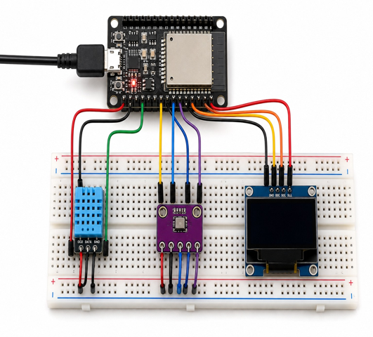
The IoT Weather Monitoring System is an intelligent solution for continuously monitoring weather conditions in real time. The ESP32 acts as the main controller and collects data from environmental sensors such as the DHT11/DHT22 temperature and humidity sensor and the BMP280 pressure sensor. The collected data is processed and transmitted to a cloud-based IoT platform via Wi-Fi, where users can view the live weather information from anywhere. The system provides accurate environmental data, making it suitable for homes, schools, industries, agricultural fields, weather stations, and research laboratories. This project demonstrates wireless communication, sensor interfacing, and cloud-based data monitoring using IoT technology.
Components Required
- ESP32 Development Board
- DHT11/DHT22 Temperature and Humidity Sensor
- BMP280 Pressure Sensor
- OLED Display (0.96" I2C) (Optional)
- Breadboard
- Jumper Wires
- USB Cable / 5V Power Supply
- Wi-Fi Connection
Working Principle
The DHT11/DHT22 sensor continuously measures the surrounding temperature and humidity, while the BMP280 sensor measures atmospheric pressure. The ESP32 collects the sensor readings, processes the data, and displays it on the OLED screen (if used). Simultaneously, the ESP32 connects to a Wi-Fi network and uploads the data to an IoT cloud platform such as ThingSpeak or Blynk. Users can monitor the live weather data through a mobile phone or web dashboard from any location with internet access. The system continuously updates the sensor readings at regular intervals, providing real-time environmental monitoring and remote access to weather information.
Experiment No: 12 Smart Air Quality Monitoring System Using ESP32
Smart Air Quality Monitoring System Using ESP32
Abstract
The Smart Air Quality Monitoring System Using ESP32 is an IoT-based environmental monitoring project designed to measure and monitor indoor air quality in real time. The system uses an air quality sensor to detect harmful gases and pollutants, along with a temperature and humidity sensor to monitor environmental conditions. The ESP32 processes the collected data and uploads it to an IoT platform through Wi-Fi, allowing users to monitor air quality remotely. This project demonstrates the use of IoT and embedded systems for creating healthier and safer environments.
Project Description
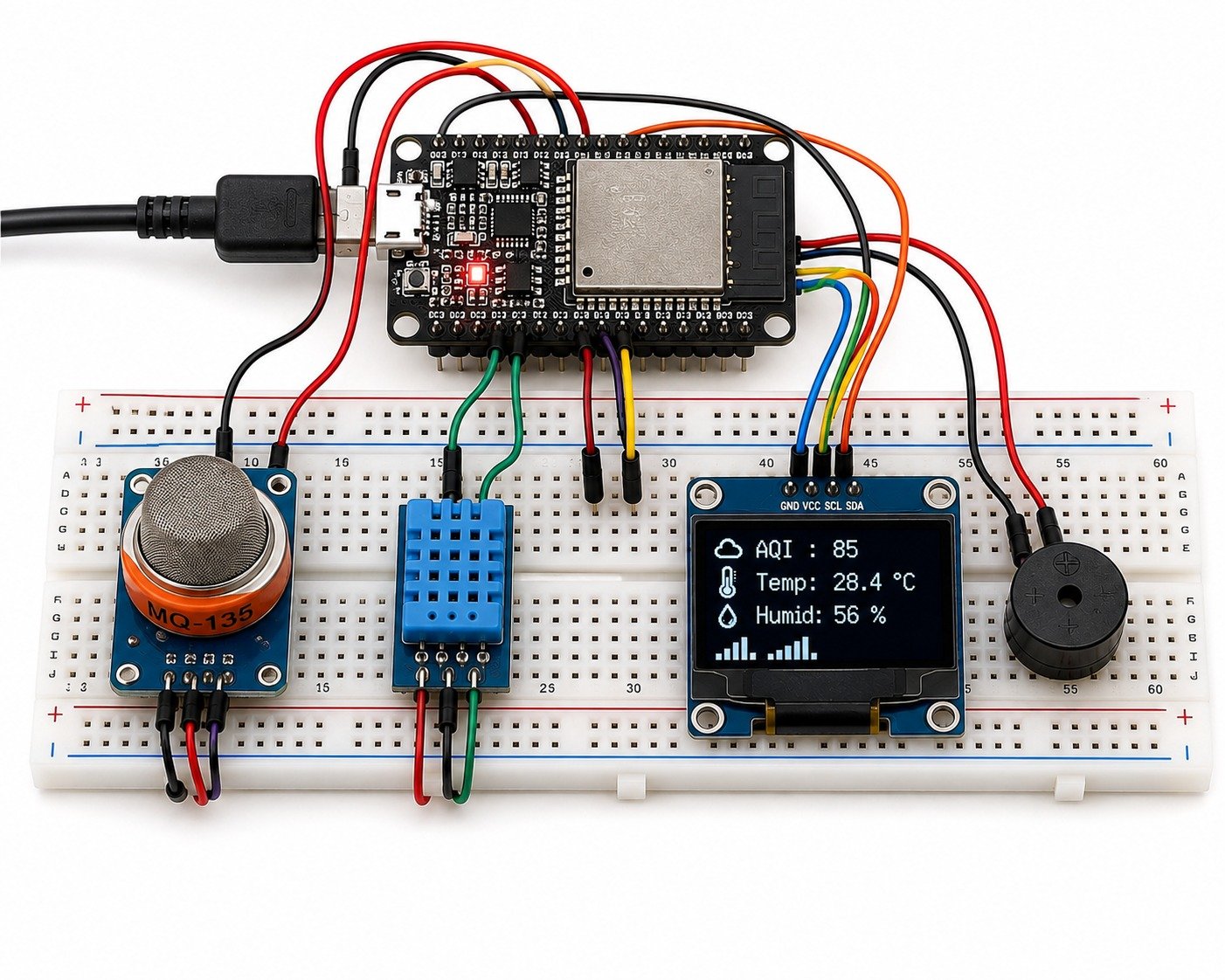
The Smart Air Quality Monitoring System continuously monitors the surrounding environment by measuring air quality, temperature, and humidity. The ESP32 serves as the central controller, collecting data from the MQ-135 air quality sensor and the DHT11/DHT22 temperature and humidity sensor. The measured values are displayed locally on an OLED display and simultaneously transmitted to a cloud-based IoT platform through Wi-Fi. If the air quality exceeds the safe limit, the system can activate a buzzer or send notifications to alert the user. This project is suitable for homes, offices, classrooms, industries, hospitals, and laboratories where maintaining healthy air quality is essential.
Components Required
- ESP32 Development Board
- MQ-135 Air Quality Sensor
- DHT11/DHT22 Temperature and Humidity Sensor
- OLED Display (0.96" I2C)
- Active Buzzer (Optional)
- Breadboard
- Jumper Wires
- USB Cable / 5V Power Supply
- Wi-Fi Connection
Working Principle
The MQ-135 sensor continuously detects the concentration of harmful gases and air pollutants, while the DHT11/DHT22 sensor measures the surrounding temperature and humidity. The ESP32 collects the sensor data, processes it, and displays the readings on the OLED display. At the same time, the ESP32 uploads the data to an IoT cloud platform through Wi-Fi, enabling users to monitor the air quality remotely using a smartphone or computer. If the pollutant level exceeds the predefined threshold, the system activates a buzzer or generates an alert notification, helping users take necessary actions to improve air quality.
Experiment No: 13 Fire Detection and Automatic Alert System Using Arduino Uno
Fire Detection and Automatic Alert System Using ESP32
Abstract
The Fire Detection and Automatic Alert System Using ESP32 is an intelligent safety project designed to detect fire at an early stage and provide instant alerts. The system uses a flame sensor to detect the presence of fire and sends the data to the ESP32 for processing. When a flame is detected, the ESP32 activates a buzzer and LED to warn nearby people. With built-in Wi-Fi capability, the system can also be extended to send notifications through IoT platforms, making it suitable for modern smart safety applications.
Project Description
The Fire Detection and Automatic Alert System is an embedded IoT-based safety solution that continuously monitors the environment using a flame sensor. The ESP32 receives the sensor data and determines whether a fire is present. If a flame is detected, the ESP32 immediately activates the buzzer and LED to provide audible and visual alerts. Since the ESP32 has built-in Wi-Fi, the project can also be integrated with cloud platforms or mobile applications for remote monitoring and emergency notifications. This low-cost and reliable system is suitable for homes, offices, laboratories, industries, warehouses, and educational institutions.
Components Required
- ESP32 Development Board
- Flame Sensor Module
- Active Buzzer
- LED
- 220Ω Resistor
- Breadboard
- Jumper Wires
- USB Cable / 5V Power Supply
- Wi-Fi Connection (Optional)
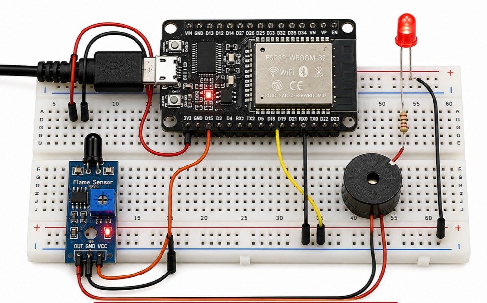
Working Principle
The flame sensor continuously monitors the surrounding area for infrared radiation emitted by fire. The detected signal is sent to the ESP32 for processing. Under normal conditions, the system remains in monitoring mode. When a flame is detected within the sensing range, the ESP32 immediately activates the buzzer and LED to provide instant alerts. If IoT functionality is enabled, the ESP32 can also transmit fire alerts to a mobile application or cloud platform through Wi-Fi. Once the flame is no longer detected, the system automatically returns to monitoring mode, ensuring continuous protection and early fire detection.
Experiment No: 14 Smart Gas Leakage Detection and Automatic Safety System Using Arduino Uno
Smart Gas Leakage Detection and Automatic Safety System Using ESP32
Abstract
The Smart Gas Leakage Detection and Automatic Safety System Using ESP32 is an IoT-based safety project that detects LPG and other combustible gas leaks using an MQ-2 gas sensor. When the gas level exceeds the safe limit, the ESP32 activates a buzzer and LED to alert users. The system can also control a relay to switch ON an exhaust fan or switch OFF electrical appliances. With built-in Wi-Fi, it can be extended to send real-time mobile notifications.
Project Description
This project continuously monitors combustible gas levels using the MQ-2 gas sensor. The ESP32 processes the sensor data and detects gas leakage. If the gas concentration exceeds the preset threshold, it activates the buzzer, LED, and relay for immediate safety action. The ESP32 can also send alerts through Wi-Fi, making the system suitable for homes, kitchens, laboratories, and industries.
Components Required
- ESP32 Development Board
- MQ-2 Gas Sensor Module
- 5V Relay Module
- Active Buzzer
- LED
- 220Ω Resistor
- Exhaust Fan / DC Motor (Simulation)
- Breadboard
- Jumper Wires
- USB Cable / 5V Power Supply
- Wi-Fi Connection (Optional)
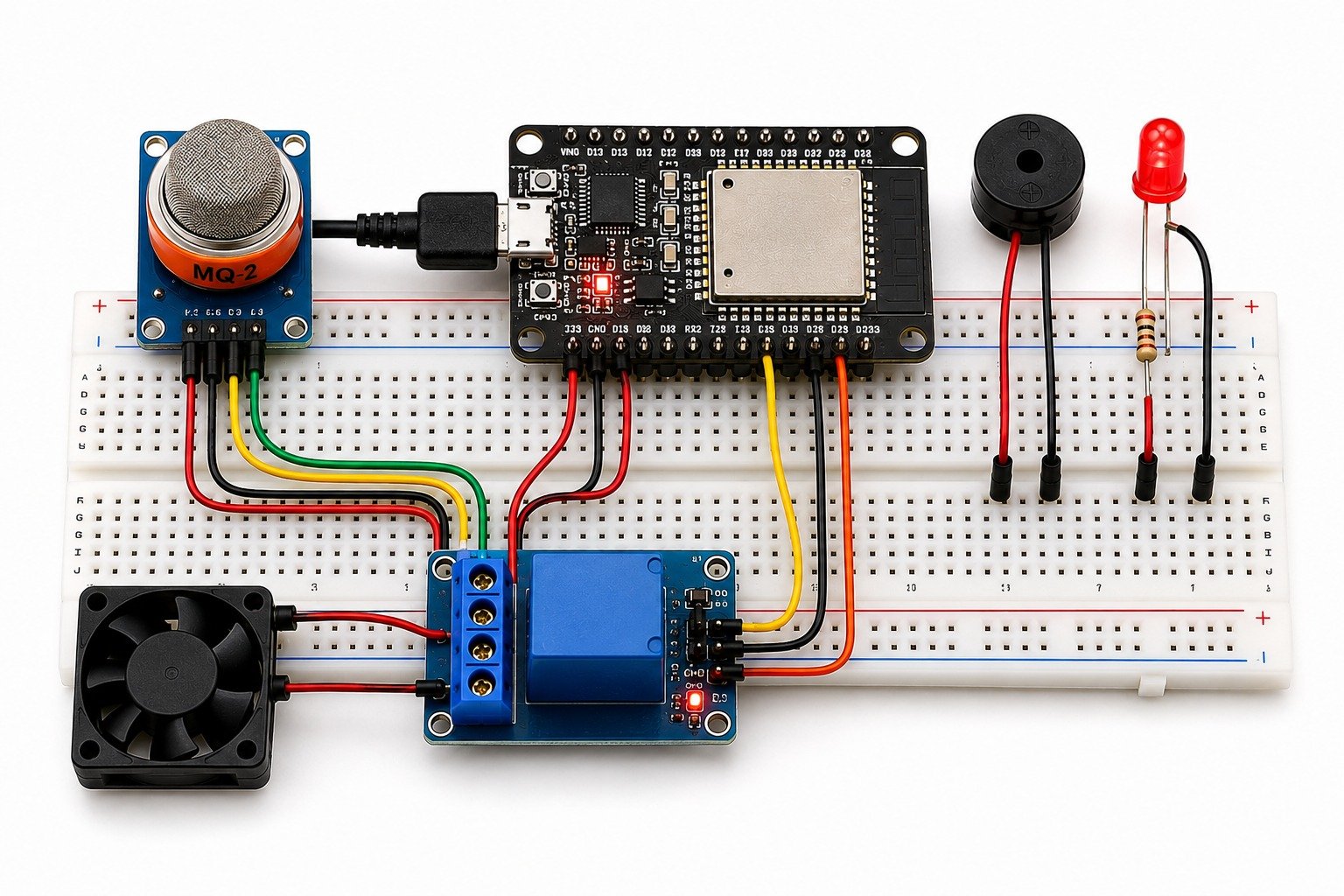
Working Principle
The MQ-2 gas sensor continuously detects combustible gases and sends the readings to the ESP32. If the gas level exceeds the preset limit, the ESP32 activates the buzzer, LED, and relay to provide alerts and control safety devices. The relay can be connected to an exhaust fan or other suitable low-voltage demonstration load to simulate automatic safety action. Once the gas level becomes safe, the system automatically returns to normal monitoring mode.
Experiment No: 15 Voice Controlled Home Automation System Using ESP32
Voice Controlled Home Automation System Using ESP32
Abstract
The Voice Controlled Home Automation System Using ESP32 is an IoT-based smart home project that allows users to control electrical appliances using voice commands through a smartphone or virtual assistant. The ESP32 connects to a Wi-Fi network and communicates with an IoT platform to receive commands. Based on the received voice command, the ESP32 controls relay modules to switch household appliances ON or OFF. This project demonstrates the integration of IoT, wireless communication, and embedded systems for smart home automation.
Project Description
The Voice Controlled Home Automation System is designed to provide a convenient and hands-free method of controlling home appliances. The ESP32 acts as the central controller and connects to the internet through Wi-Fi. Voice commands given through applications such as Google Assistant or Alexa are transmitted to the ESP32 via an IoT platform like Blynk or Sinric Pro. The ESP32 processes the received command and operates the corresponding relay module to control devices such as lights, fans, and other electrical appliances. This project offers an efficient, user-friendly, and energy-saving solution for modern smart homes and is suitable for residential buildings, offices, and IoT learning applications.
Components Required
- ESP32 Development Board
- 2/4 Channel Relay Module
- Wi-Fi Connection
- Light Bulb / Fan (Load Simulation)
- Breadboard
- Jumper Wires
- USB Cable / 5V Power Supply
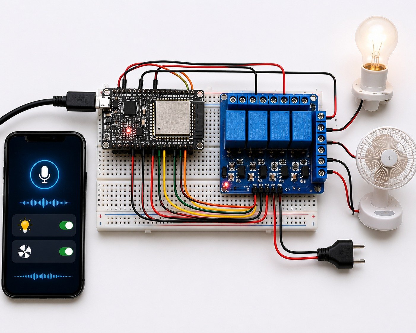
Working Principle
The ESP32 connects to a Wi-Fi network and communicates with an IoT cloud platform. When the user gives a voice command through Google Assistant, Alexa, or a mobile application, the command is sent to the ESP32 over the internet. The ESP32 processes the command and activates the appropriate relay channel to switch the connected appliance ON or OFF. The system continuously listens for new commands, allowing users to control multiple electrical devices remotely using simple voice instructions. This provides a smart, convenient, and efficient home automation solution.
Experiment No: 16 Fingerprint-Based Smart Door Lock System Using Arduino Uno
Fingerprint-Based Smart Door Lock System Using ESP32
Abstract
The Fingerprint-Based Smart Door Lock System Using ESP32 is an IoT-based security project that provides secure and keyless access using biometric authentication. The system uses a fingerprint sensor to identify authorized users. When a valid fingerprint is detected, the ESP32 unlocks the door using a servo motor or electronic door lock. Unauthorized access activates a buzzer and LED, while the built-in Wi-Fi enables remote monitoring and future IoT integration.
Project Description
The Fingerprint-Based Smart Door Lock System replaces traditional keys with fingerprint authentication for improved security. The ESP32 communicates with the fingerprint sensor to verify registered fingerprints stored in its memory. If a valid fingerprint is detected, the ESP32 unlocks the door for a few seconds and then locks it automatically. If an unauthorized fingerprint is scanned, the system keeps the door locked and activates the buzzer and LED. With built-in Wi-Fi, the system can also be integrated with IoT platforms for remote monitoring and notifications.
Components Required
- ESP32 Development Board
- Fingerprint Sensor Module (R307/AS608)
- Servo Motor or Solenoid Door Lock
- 5V Relay Module (Optional)
- Active Buzzer
- LED
- Breadboard
- Jumper Wires
- USB Cable / 5V Power Supply
- Wi-Fi Connection (Optional)
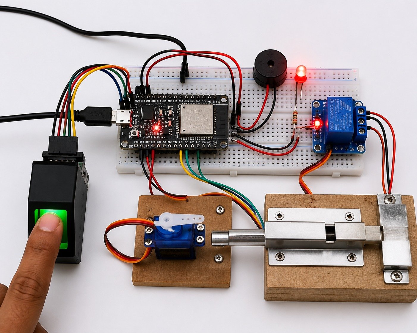
Working Principle
The fingerprint sensor scans the user’s fingerprint and sends the data to the ESP32 for verification. If the fingerprint matches a registered user, the ESP32 activates the servo motor or door lock to unlock the door for a few seconds before locking it again. If the fingerprint is not recognized, the ESP32 keeps the door locked and activates the buzzer and LED. The system continuously monitors for new fingerprint scans and can also send alerts through Wi-Fi when IoT features are enabled.
Experiment No: 17 Autonomous Line Following Robot with Obstacle Avoidance Using Arduino Uno
Autonomous Line Following Robot with Obstacle Avoidance Using ESP32
Abstract
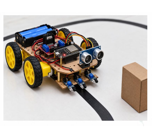
The Autonomous Line Following Robot with Obstacle Avoidance Using ESP32 is an intelligent robotic system that follows a predefined path while automatically avoiding obstacles. The robot uses IR sensors for line tracking and an ultrasonic sensor for obstacle detection. The ESP32 processes the sensor data and controls the motors through a motor driver for smooth navigation. With built-in Wi-Fi, the robot can also be extended for IoT-based monitoring and control.
Project Description
The Autonomous Line Following Robot is an embedded robotic project designed for automatic navigation without human intervention. The ESP32 continuously receives input from the IR sensors to follow the line and controls the motors through the L298N motor driver. The ultrasonic sensor detects obstacles in front of the robot. If an obstacle is detected, the ESP32 stops the robot, changes its direction to avoid the obstacle, and then resumes line following. This project is suitable for robotics learning, industrial automation, warehouse robots, and autonomous navigation research.
Components Required
- ESP32 Development Board
- IR Sensor Module (Line Tracking Sensors)
- Ultrasonic Sensor (HC-SR04)
- L298N Motor Driver Module
- BO Motors (DC Geared Motors)
- Robot Chassis with Wheels
- Caster Wheel
- Battery Pack (9V/12V)
- Jumper Wires
- USB Cable
Working Principle
The IR sensors continuously detect the black line and send the data to the ESP32. Based on the sensor readings, the ESP32 controls the motor driver to move the robot along the path. Simultaneously, the ultrasonic sensor detects obstacles ahead. If an obstacle is found, the ESP32 stops the robot, changes its direction to avoid the obstacle, and then continues following the line automatically.
Smart IrExperiment No: 18 rigation System Using Arduino Uno
Smart Irrigation System Using ESP32
Abstract
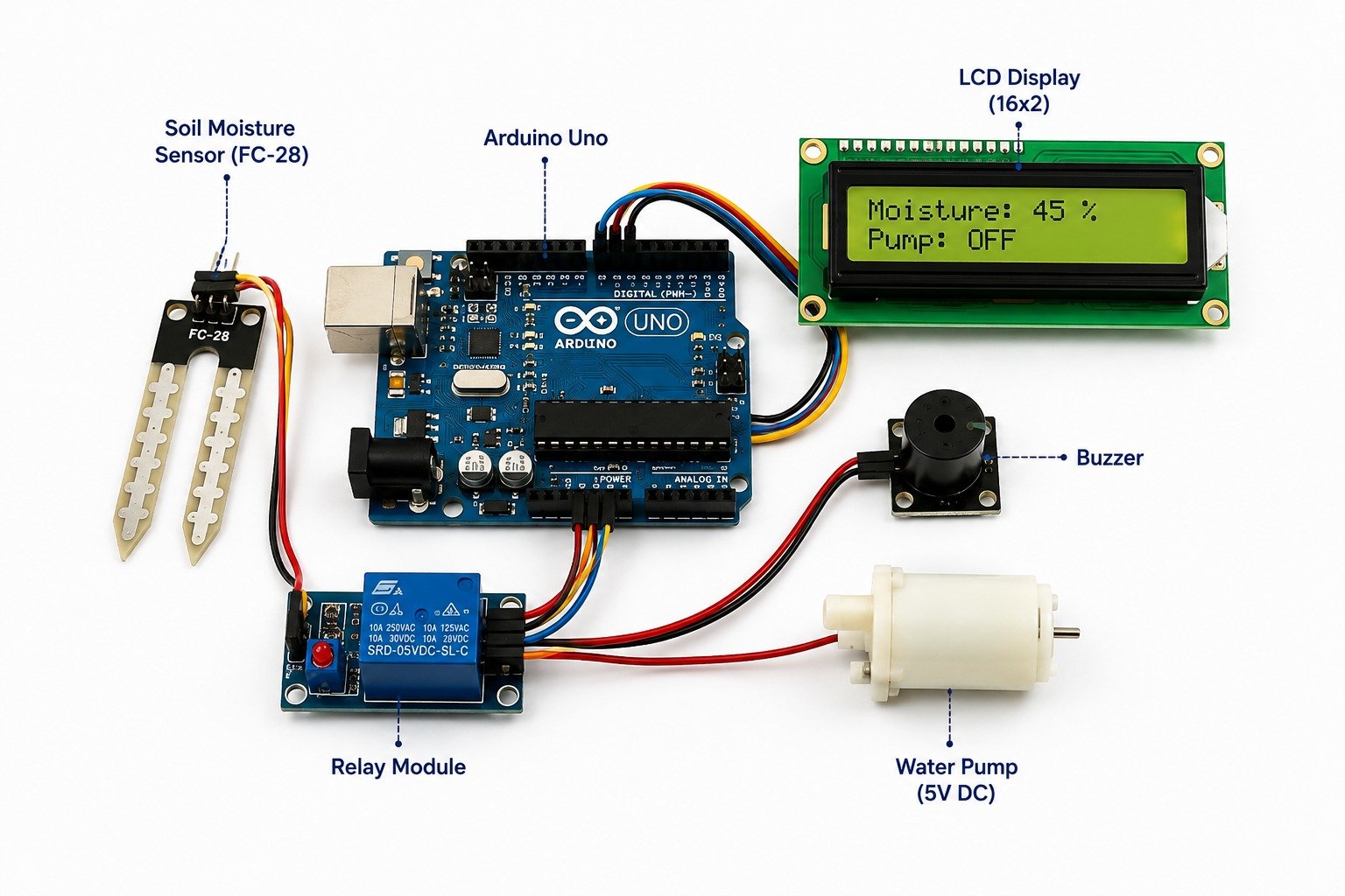
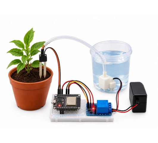
The Smart Irrigation System Using ESP32 is an IoT-based agricultural automation project designed to optimize water usage by irrigating plants only when required. The system uses a soil moisture sensor to monitor soil conditions and automatically controls a water pump through a relay module. With the ESP32’s built-in Wi-Fi, it can also be extended for remote monitoring and control through IoT platforms.
Project Description
The Smart Irrigation System continuously monitors soil moisture using a soil moisture sensor. The ESP32 processes the sensor data and compares it with a predefined threshold. If the soil becomes dry, the ESP32 activates the relay module to switch ON the water pump. Once the required moisture level is reached, the pump is switched OFF automatically. This project reduces water wastage, eliminates manual irrigation, and provides an efficient solution for home gardens, farms, greenhouses, and smart agriculture applications.
Components Required
|
|
Working Principle
The soil moisture sensor continuously measures the moisture level of the soil and sends the data to the ESP32. The ESP32 compares the sensor value with a predefined threshold. When the soil becomes dry, it activates the relay module to turn ON the water pump. Once the desired moisture level is reached, the ESP32 switches OFF the pump automatically. The system continuously monitors the soil and repeats the process whenever irrigation is required, ensuring efficient water management and healthy plant growth.
Experiment No: 19 IoT-Based Smart Doorbell with Camera Using ESP32-CAM
IoT-Based Smart Doorbell with Camera Using ESP32-CAM
Abstract
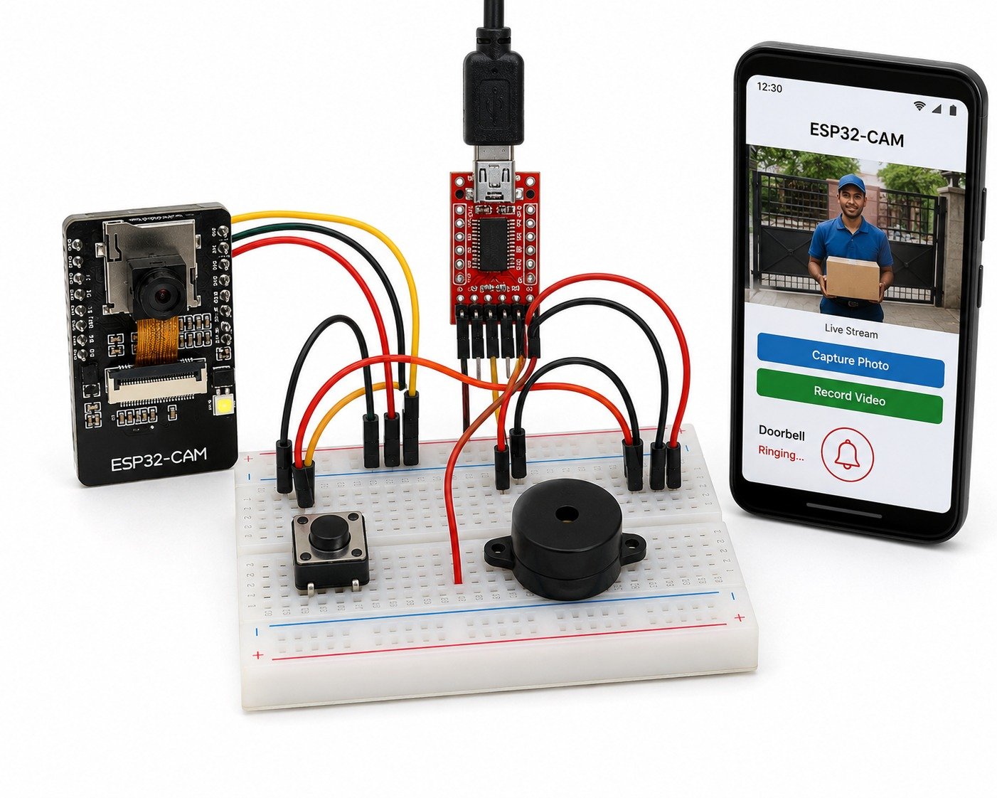
The IoT-Based Smart Doorbell with Camera Using ESP32-CAM is a smart home security project that enables users to monitor visitors remotely. The system uses an ESP32-CAM module to capture images or stream live video when the doorbell button is pressed. The captured information is transmitted through Wi-Fi, allowing homeowners to view visitors using a smartphone or computer. This project demonstrates the integration of IoT, wireless communication, and embedded systems for modern home security.
Project Description
The IoT-Based Smart Doorbell with Camera is an intelligent security system that allows users to identify visitors without opening the door. The ESP32-CAM acts as both the microcontroller and camera module, capturing images or live video whenever the doorbell button is pressed. The captured data is sent to a mobile application or web interface through a Wi-Fi connection, enabling remote monitoring from anywhere. A buzzer also alerts people inside the house when someone is at the door. This project is suitable for homes, apartments, offices, and smart building applications, providing a secure and convenient visitor monitoring solution.
Components Required
|
|
Working Principle
The ESP32-CAM remains connected to a Wi-Fi network and continuously monitors the doorbell button. When a visitor presses the button, the ESP32-CAM captures an image or starts live video streaming. The captured data is transmitted to the user’s smartphone or web application through the internet, allowing the homeowner to identify the visitor remotely. At the same time, the buzzer sounds to notify people inside the house. After the event is completed, the system returns to standby mode and continues monitoring for the next visitor, ensuring reliable and secure visitor surveillance.
Experiment No: 20 Smart Water Level Monitoring and Automatic Pump Control System Using Arduino Uno
Smart Water Level Monitoring and Automatic Pump Control System Using ESP32
Abstract
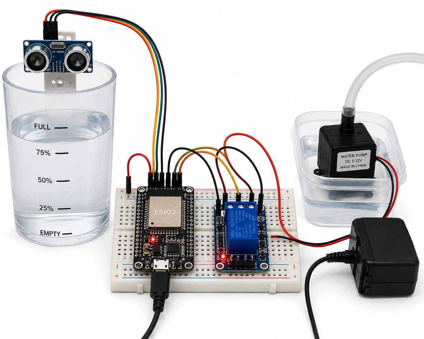
The Smart Water Level Monitoring and Automatic Pump Control System Using ESP32 is an IoT-based automation project designed to monitor the water level in a storage tank and control the water pump automatically. The system uses an ultrasonic sensor to measure the water level, while the ESP32 processes the sensor data. When the water level is low, the pump starts automatically, and when the tank becomes full, the pump stops. With built-in Wi-Fi, the system can also be extended for remote monitoring through IoT platforms.
Project Description
The Smart Water Level Monitoring and Automatic Pump Control System is an embedded IoT solution for efficient water management. The ultrasonic sensor continuously measures the water level inside the tank and sends the data to the ESP32. Based on the measured level, the ESP32 controls a relay module to switch the water pump ON or OFF automatically. The system ensures continuous monitoring, prevents water overflow, reduces water wastage, and supports remote monitoring through Wi-Fi. It is suitable for homes, apartments, industries, farms, and educational laboratories.
Components Required
|
|
Working Principle
The ultrasonic sensor continuously measures the water level inside the tank and sends the readings to the ESP32. The ESP32 compares the measured level with predefined minimum and maximum limits. When the water level falls below the minimum level, the ESP32 activates the relay module to switch ON the water pump. Once the tank reaches the maximum level, the ESP32 switches OFF the pump automatically. The system continuously monitors the tank, ensuring efficient water management and preventing overflow.